| Individual surfaces that were constructed from an underlying tile-map. |
This is part 2 of 5 in a series describing how to implement 2D-platformer AI, pathfinding, and character movement. You can see a working example of these techniques in the Surfacer framework for Godot.
Part 2: AI, graphs, and surfaces
Adding AI
The AI for movement in any video game is almost always calculated by first representing the level as a graph and then searching the graph to find a path to our destination. The field of graph theory is well established, and once we have a graph, finding a path through it is just a matter of applying a pre-existing search algorithm.
 |
| A directed graph. A typical problem might be to find the shortest path from A to B. |
Defining a graph
The trick is how to represent a level as a graph.
For most games, a level is defined by using a tile-map to place tiles within a grid.
For top-down games, this graph representation is straight-forward. A node represents a place that the character can stand, and an edge represents how the character can move from one node to another. Typically, each tile in the world grid is a node, and there can be an edge from each node to each of its four neighbors—unless there's a wall or other obstacle in the way.
 |
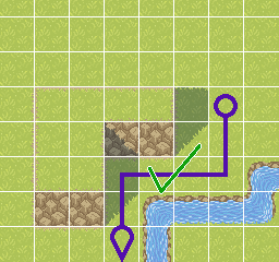
| In a top-down game, this grid-based path makes sense. It would seem normal for a character to walk along this path. |
However, for platformer games, it is much less clear how to encode the level as a graph. We still want nodes to represent places the character can rest, and edges to represent movement between nodes. So nodes must be positions along floor surfaces (or maybe along wall or ceiling surfaces if the character can climb). But that means that we must first determine where the surfaces are, according to the tiles in our level's tile-map. For example, if you have a 3x3 square of connected tiles, then there are 3-tile-long floor, left-wall, right-wall, and ceiling surfaces along the outside of the 3x3 square, but there are no internal surfaces within the interior of the 3x3 square.
 |
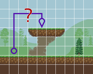
| In a platformer game, this grid-based path doesn't make sense. We expect a character to jump with parabolic motion based on physics. |
The edges in a platformer level graph would then represent movement from one surface to the next—or possibly between two positions along the same surface. The primary type of movement in a platformer is a jump, so we need to be able to somehow encode a jump as an edge in our graph. Some of the important pieces of information for a jump are:
- The start and end positions
- Which surfaces the start and end positions lie along
- The duration of the jump
- The start and end velocity
- The trajectory of the jump—i.e., the character's position during each frame for the duration of the jump
- The sequence and timing of corresponding controller input presses and releases that would produce the movement of the jump
Note that there can also be other types of movement in a platformer—such as walking, climbing, and falling—and each of these types of movement will need to be represented slightly differently as edges in our graph.
 |
| A possible path through a platform graph. This is an example of some distinct surfaces, and edge trajectories ending at specific positions along these surfaces. |
Nodes: Parsing tile-maps into surfaces
So now we know that our platformer AI is going to rely on representing the level as a graph, and we know that we need the nodes of this graph to correspond to positions along "surfaces". But how do we calculate what these surfaces are?
We define the collidable shape of a level using tile-maps. A single "surface" is then formed by a collection of tiles that connect along one side. There are four types of surfaces: tile-bottom-side, tile-top-side, tile-right-side, tile-left-side—or floor, ceiling, left-wall, right-wall, respectively.
The algorithm
NOTE: The following algorithm assumes that the given tile-map only uses tiles with convex collision boundaries. This is a pretty reasonable constraint. If you need convex shapes, you could always just form them from pairs of adjacent tiles.
Parse individual tiles into their constituent surfaces
- [Source code]
- Map each tile-map cell into a polyline that corresponds to the top-side/floor portion of its collision polygon.
- Calculate whether the collision polygon's vertices are specified in a clockwise order.
- Use this to determine the iteration step size.
- `step_size = 1` if clockwise; `step_size = -1` if counter-clockwise.
- Regardless of whether the vertices are specified in a clockwise order, we will iterate over them in clockwise order.
- Find both the leftmost and rightmost vertices.
- Start with the leftmost vertex.
- If there is a wall segment on the left side of the polygon, then this vertex is part of it.
- If there is no wall segment on the left side of the polygon, then this vertex must be the cusp between a preceding bottom-side/ceiling segment and a following top-side/floor segment (i.e., the previous segment is underneath the next segment).
- Even if there is no segment along one side, we store a surface for that side.
- This degenerate surface is only represented by a single point.
- Iterate over the following vertices until we find a non-wall segment.
- This could be the first segment—the one connecting to the leftmost vertex.
- Wall segments are distinguished from floor/ceiling segments according to their angle. This is configurable, but typically, a segment up to 45-degrees is a floor/ceiling and a segment steeper than 45-degrees is a wall.
- This non-wall segment must be the start of the top-side/floor polyline.
- Iterate, adding segments to the result polyline, until we find either a wall segment or the rightmost vertex.
- We then also save a mapping from a tile-map cell index to each of the different surfaces we've calculated as existing in that cell.
- This is important for being able to later get references to surfaces according to arbitrary positions.
- Repeat the above process for the right-side, left-side, and bottom-side surfaces.
Remove internal surfaces
NOTE: This will only detect internal surface segments that are equivalent with another internal segment. But for grid-based tiling systems, this can often be enough.
- [Source code]
- Check for pairs of floor+ceiling segments or left-wall+right-wall segments, such that both segments share the same vertices.
- Remove both segments in these pairs.
Merge any connecting surfaces
- [Source code]
- Iterate across each floor surface A.
- Nested iterate across each other floor surface B.
- Ideally, we should be using a spatial data structure that allows us to only consider nearby surfaces during this nested iteration (such as an R-Tree).
- Check whether A and B form a "continuous" surface.
- A and B are both polylines that only have two end points.
- Just check whether either endpoint of A matches either endpoint of B.
- Actually, our original tile-map parsing results in every surface polyline being stored in clockwise order, so we only need to compare the end of A with the start of B and the start of A with the end of B.
- If they do match:
- Merge B into A.
- Optionally, remove any newly created redundant internal colinear points.
- Remove B from the surface collection.
- Repeat the iteration until no merges were performed.
Record adjacent neighbor surfaces
- [Source code]
- Every surface should have both adjacent clockwise and counter-clockwise neighbor surfaces.
- Use a similar process as above for finding surfaces with matching end positions.
- After recording neighbor surfaces, we can also calculate and record the bounding box for the entire connected region formed from all transitive neighbor surfaces [source code].
 |
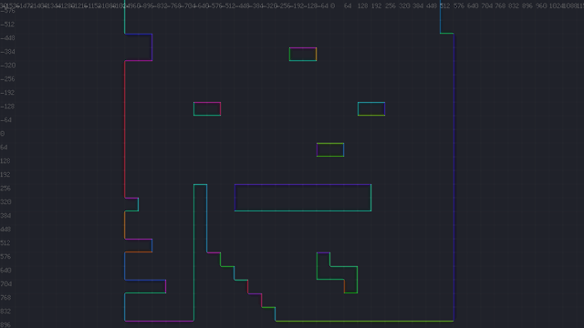
| Distinct surfaces, parsed from an underlying tile-map. |

Comments
Post a Comment